Piezoelectric ultrasonic motor WUMoLL000 description - Wischnewskyi Ultrasonic Motors


PRODUCTS
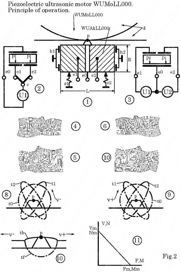
PIEZOELECTRIC ULTRASONIC MOTOR WUMoLL000.
Principle of operation.
At position 1 (see Fig. 2), a WUMoLL000 piezoelectric ultrasonic motor is shown schematically. The motor contains a WUAkLL000 piezoelectric ultrasonic actuator, with the output of the common electrode e0 and with the connections of the exciting electrodes e1, e2.
Actuator WUAkLL00 is movably mounted in holders h1, h2. The actuator friction member WUFe000 is pressed by the springs S1, S2 against the friction layer of the movable member d1. А movable element can be made in the form of a rotor or slider. The rotor makes an angular or rotational movement. The slider makes a rectilinear motion.
Position 2 shows a single-phase excitation circuit of the motor.
With single-phase excitation, the excitation voltage U1 with a frequency of Fw.o is supplied through the switch s to the common actuator electrode e0 and to the excitation electrode e1 or to the excitation electrode e2.
In both cases in the actuator, two standing acoustic waves of the same frequency are simultaneously excited. The second mode of the acoustic wave propagating along the length L of the actuator and the first mode of the acoustic wave propagating along its width B.
In the first case, the actuator oscillates as shown in positions 4, 5. In the second case, the actuator oscillates as shown in positions 6.7.
If the actuator is in a free state, i.e. since its friction element is not pressed against the friction layer of the movable element, then all points and point p of the friction element move along circular trajectories t2 or along the elliptic trajectories t1 or along with t2. The direction of movement of the points is shown by arrows with an index +/- V, as shown at positions 8.9.
With a constant length L of the actuator, the shape of the elliptical trajectories t1 or t2 and their slope depend on the width B of the actuator or on the L / B ratio.
At position 3, a two-phase excitation circuit of motor 1 is shown. With two-phase excitation, one excitation voltage U1 is supplied to the common electrode e0 and to the excitation electrode e1. The second voltage U2 is applied to the common electrode e0 and to the exciting electrode e2. Both voltages have a frequency of Fw.o.
In this case, four standing acoustic waves are excited in the actuator. A summation of the propagating standing acoustic waves in the actuator occurs. As a result, two standing acoustic waves are formed in the actuator and the actuator oscillates similarly to the previous case shown at positions 4 ... 7.
Under two-phase excitation, the shape of the trajectories of the points of the friction element and the point p depends both on the L / B ratio and on the phase shift between the voltages U1 and U2.
If the friction element is pressed against the friction surface of the movable element, then the trajectories of the points of the friction element and the point p have two characteristic sections. The plot of free movement tf of the friction element and the plot of the loaded movement tb, as shown at position 10.
In the case of a loaded movement between the friction element and the friction layer, a friction force arises, through which the force from the actuator is transmitted to the movable element.
If the movable element is not loaded, then it moves with a maximum linear speed Vm or rotational speed Nm.
If the movable element is inhibited by the load, then the maximum force Fm or maximum torque Mm acts on the load.
The maximum speed Vm and the maximum force Fm determine the mechanical characteristic of the motor, which is ideally linear, as shown in position 11.
Piezoelectric ultrasonic motor WUMoLL000.
Design description.
The WUMoLL000 piezoelectric ultrasonic motor (see Fig. 2) includes a WU -LL000 piezoelectric actuator consisting of a WUPeLL000 piezoelectric element (see Fig. 1), to which one WUFe000 friction element is connected.
The piezoelectric actuator of the motor is installed in the motor housing and is held in it with the help of the resonant holders h1, h2. The actuator holders are made so that they rigidly enough keep the actuator from displacing it along its lateral planes. At the same time, the holders allow the actuator to move freely in the direction perpendicular to its lateral planes.
The actuator holders are arranged so that they isolate the motor housing from the penetration of ultrasonic acoustic vibrations of the actuator into it. This is ensured by the resonant wings of the holders holding the actuator. The outer ends of the wings are tightly pressed against the end faces of the actuator, and the inner sides are fixed to the base of the body.
The clamp of the friction element of the actuator to the friction surface of the movable element is carried out by two pressing springs s1, s2. Clamping springs generate the optimal clamping force of the friction element to the friction surface of the movable element. The optimal clamping force ensures the emergence of the optimal frictional force between the friction element and the friction surface of the movable element. The optimum friction force ensures the transmission of the maximum pulling force of the motor from the actuator to the movable element.
Products description:
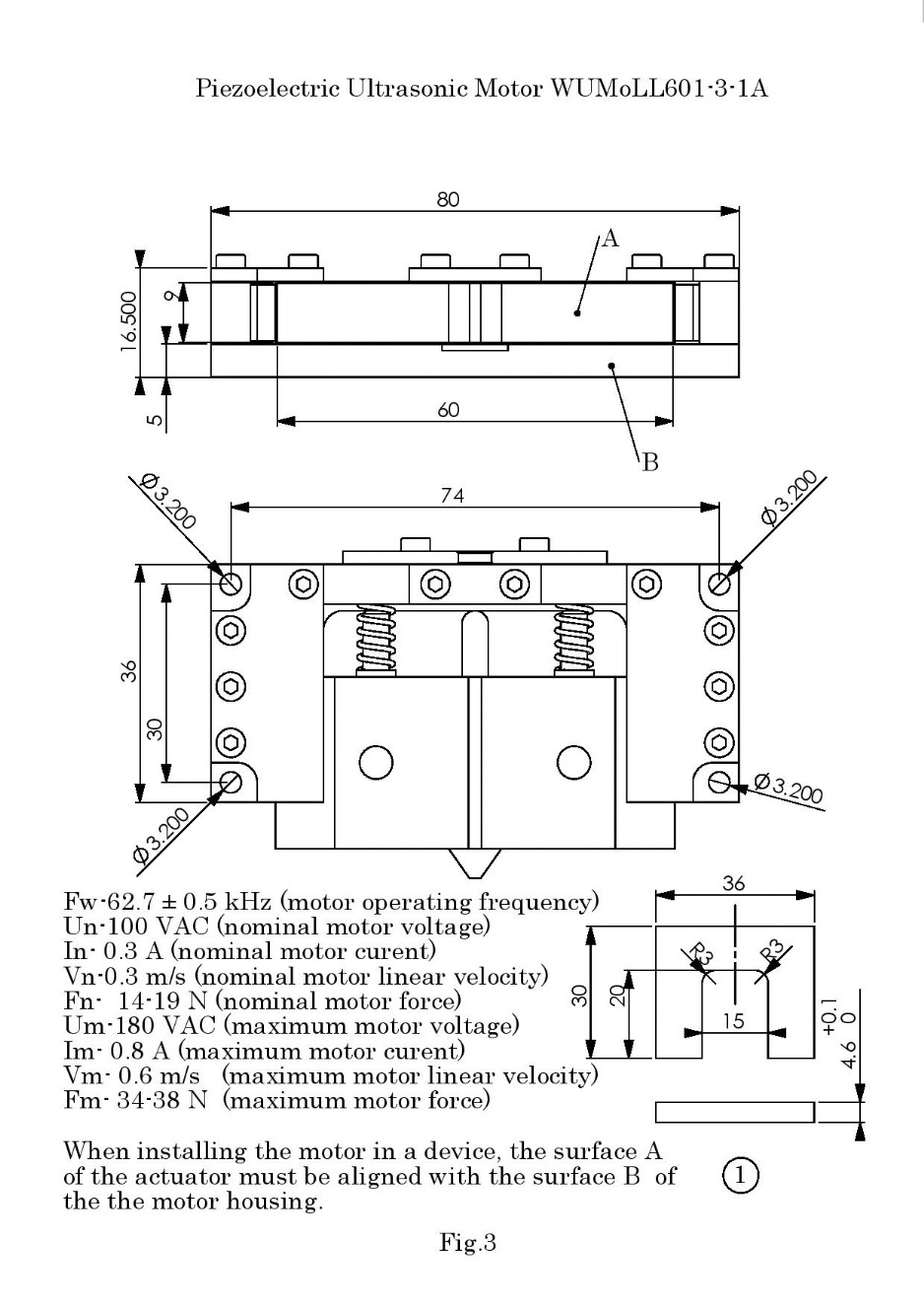
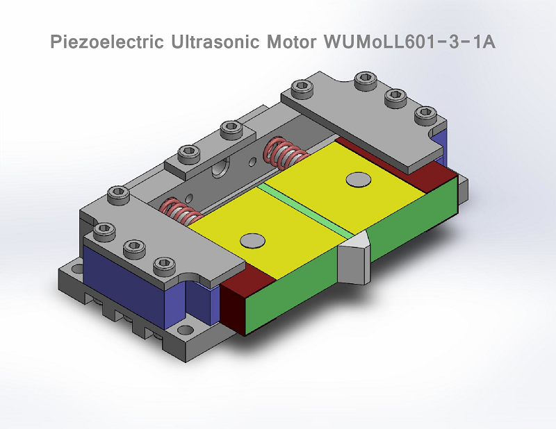
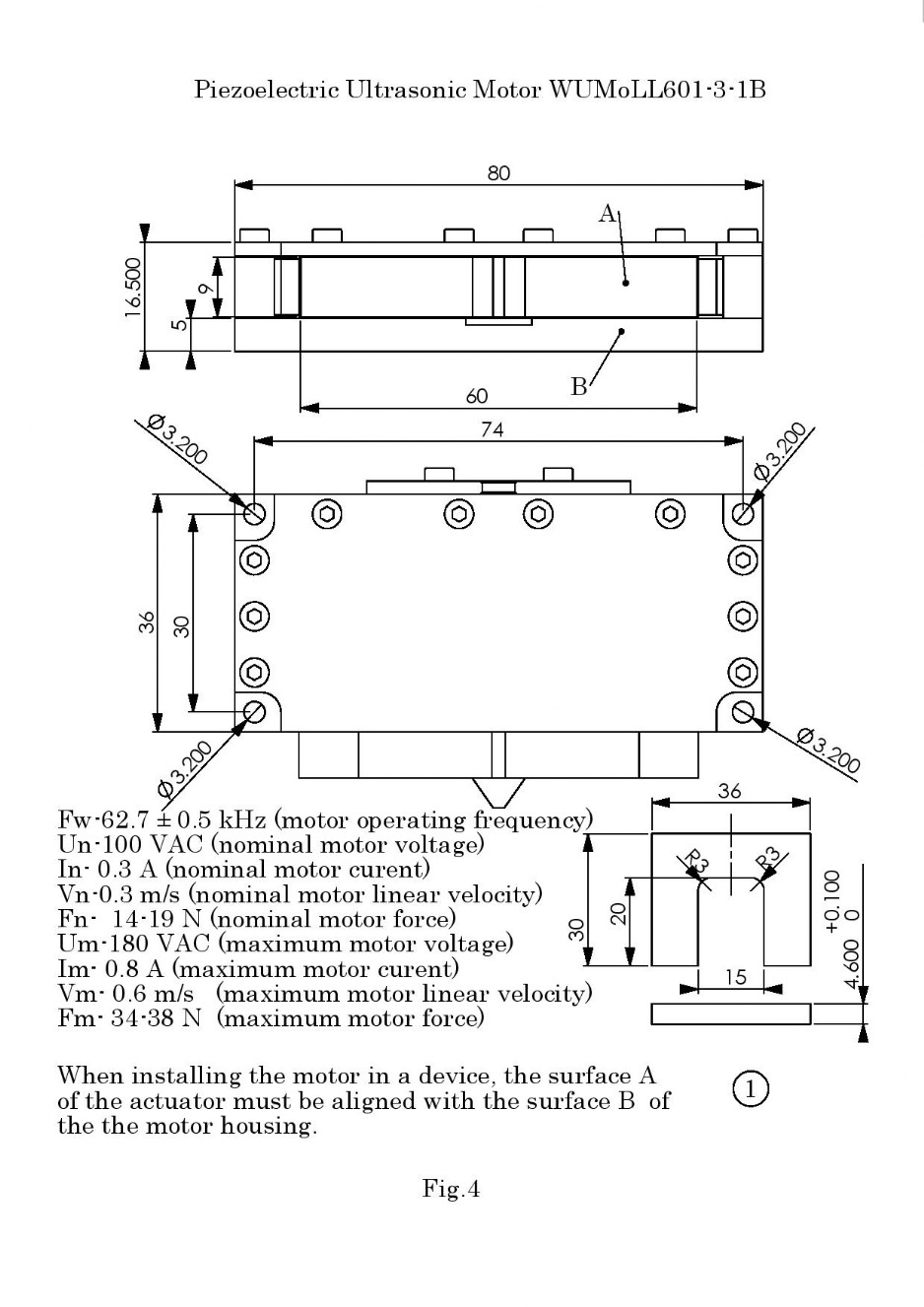
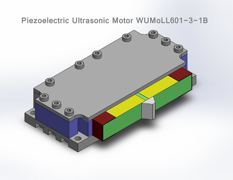
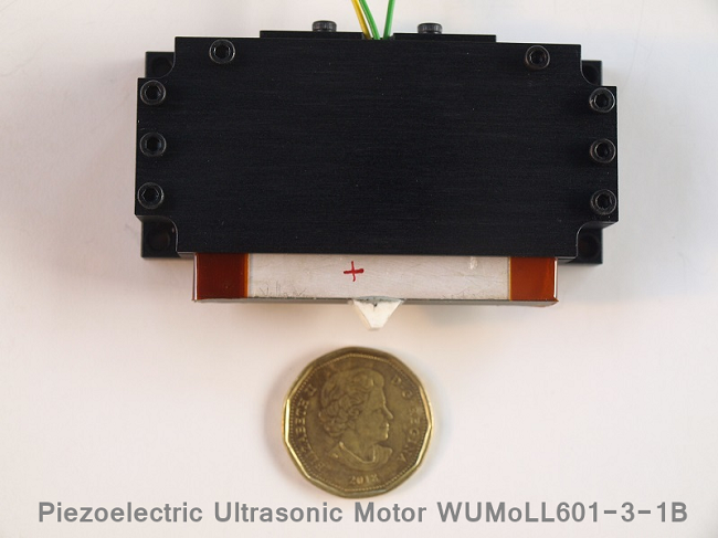
Ultrasonic Piezoelectric Type Motor WUMoLL601-3-1A, WUMoLL601-3-1B.
WUMoLL601-3-1A, WUMoLL601-3-1B motors include WUAkLL601-3-1 actuators, consisting of a WUPeLL601-3 piezoelectric element with three electrodes and one WUFe200 friction element.
Ultrasonic Piezoelectric Type Motors WUMoLL601-4-1A, WUMoLL601-4-1B.
WUMoLL601-4-1A, WUMoLL601-4-1B motors include WUAkLL601-4-1 actuators, consisting of a WUPeLL601-4 piezoelectric element with four electrodes and one WUFe200 friction element.
In all these motors, the length L of the actuators is 60 mm, the thickness D is 9 mm.
Figure 3 shows the appearance of the motors WUMoLL601-3-1A, WUMoLL601-4-1A, these motors have an open casing.
Figure 4 shows the appearance of the motors WUMoLL601-3-1B, WUMoLL601-4-1B, these motors have a closed housing.
In all designs of motors, during their installation, in order to obtain optimal clamping force, the pressing springs must be compressed by a predetermined value, which is determined by the geometry of the springs.
The amount of compression of the springs or the pressing force is achieved by combining the lateral surface of the actuator with the lateral surface of the motor housing. The compression of the springs is as follows.
- The motor is installed on the installation surface of the device in which it should work.
- The friction element of the actuator rests on the friction surface of the movable element.
- In the gap between the friction surface of the movable element and the lateral surface of the actuator, a calibration U-shaped plate is inserted, the thickness of which is 0.1 mm greater than the height of the friction element. A drawing of a u-shaped plate is shown at position 1, figure 3, figure 4.
- The motor housing is pushed onto the actuator until the lateral surface A of the actuator is aligned with the side surface B of the housing (see figure 3, figure 4).
- The motor housing is mounted on the mounting surface with fixing screws.
- After that take out the calibration u-shaped plate.
The piezoelectric ultrasonic motors WUMoLL601-3-1A and WUMoLL601-3-1B are shown below: