Control electronics WUDr001 for ultrasonic motors - Wischnewskyi Ultrasonic Motors


PRODUCTS
CONTROL ELECTRONICS PCB WUDr000 FOR ULTRASONIC MOTOR WUMoLL000.
Design and principle of operation.
The WUDr001 control electronics PCB is designed to generate an electrical voltage exciting the WUAkLL000 actuator of the WUMoLL000 ultrasonic piezoelectric motor.
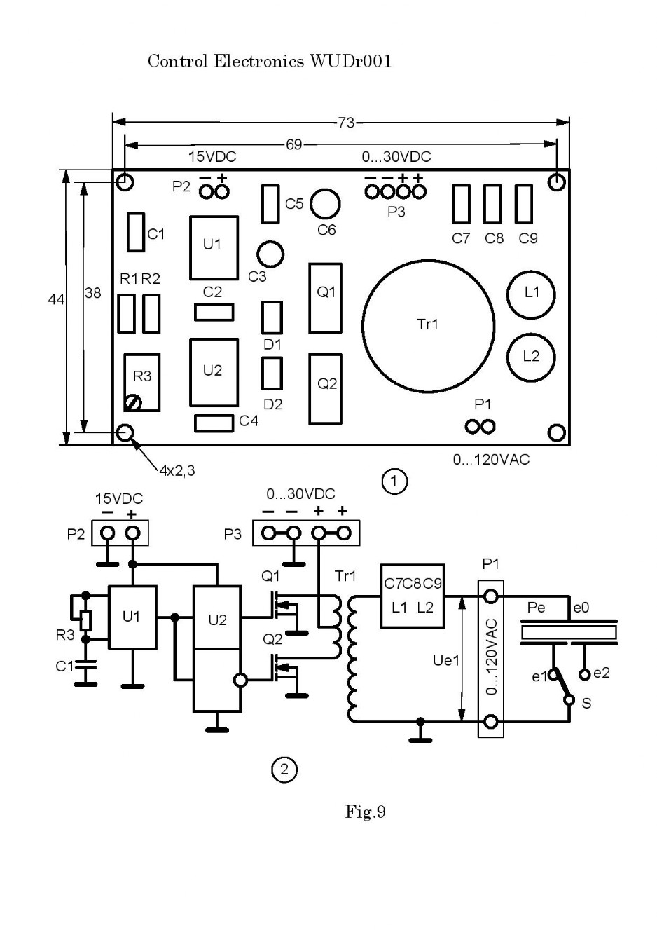
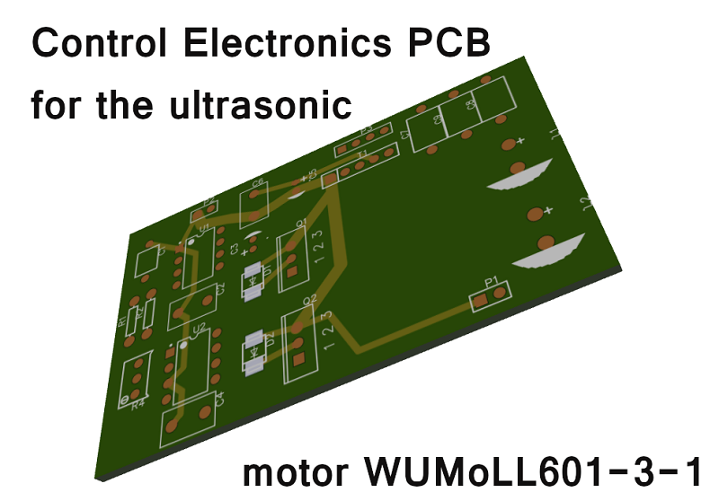
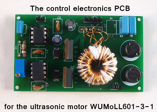
Fig.9 shows control electronics PCB with installed electronic components on it.
The WUDr001 control electronics PCB is designed to generate an electrical voltage exciting the WUAkLL000 actuator of the WUMoLL000 ultrasonic piezoelectric motor.
Fig.9 shows control electronics PCB with installed electronic components on it.
Fig. 9, position 2, shows an electronic block diagram of a control electronics PCB.
The control electronics PCB contains a master oscillator made on a U1 chip. It contains frequency setting elements R3, C1.
The generator produces a square wave voltage, the frequency of which is equal to the operating frequency of the ultrasonic piezoelectric motor.
Changing the resistance of the variable resistor R3, allows to adjust the frequency of the generator, making it equal to the operating frequency of the ultrasonic piezoelectric motor.
The generator is connected to two matching amplifiers made on a U2 chip. Matching amplifiers are connected to transistor bases of a push-pull power amplifier with step-up transformer Tr1.
A square wave voltage is generated on the secondary winding of the step-up transformer, which is supplied through the filter C7, C8, C9, L1, L2 to the electrodes e0, e1, e2 of the piezoelectric element Pe.
The ultrasonic piezoelectric motor is driven by a sinusoidal exciting voltage Ue1.
The frequency of the exciting voltage Ue1 is equal to the frequency of the master oscillator i.e. operating frequency of an ultrasonic piezoelectric motor.
Ue1 indicates the constant voltage that is applied to the pins of connector P3.
Change in voltage at the pins of connector P3.
Changing the voltage amplitude Ue1 changes the speed of the moving element.
When several short pulses are applied to the contacts of connector P3, a “constant” voltage of the exciting voltage Ue1 is generated in the form of several short radio pulses, each of which can contain 3 ... 5 periodic oscillations of the exciting voltage.
In this mode of operation of the motor, the movable element Me makes a stepwise movement in which the number of steps corresponds to the radio pulses arriving at the electrodes of the piezoelectric element Pe of the motor actuator.
When one short pulse of a "constant" voltage of the exciting voltage Ue1 is applied to the contacts of connector P3, it is generated in the form of one short radio pulse. In this moving element, I can have one short step.
A change in the direction of motion of the movable element Me occurs by switching the switch S from position e1 to position e2. In this case, the exciting voltage is applied to the common electrode e0 and to one exciting electrode e1 or to the second exciting electrode e2.
The use of a voltage regulator applied to the contacts of the P3 connector and the speed or position sensor of the movable element Me allows implementing a stabilization system for the speed of the moving element Me or a positioning system for the moving element Me in which the speed stability can reach hundredths of a percent and the positioning accuracy can exceed a fraction of a nanometer.