Piezoelectric Ultrasonic motors type WUMoRC... - Wischnewskyi Ultrasonic Motors


PRODUCTS
Ultrasonic piezoelectric motors type WUMoRC.
Ultrasonic piezoelectric motors type WUMoRC are described in such patents:
US4453103A, DE3213275C2, FR2525410B1, GB2118374B, JPS58192474A, SE452932 B, CA1190953A, AU556659B2, AU824 9982A, AT384912B, NL8201578A, IT1158293, US6867532B2.
Unlike electric motors operating on electromagnetic interaction between the stator and the rotor, the piezoelectric motor operates on frictional interaction of the stator and the rotor; that is, at the expense of frictional forces, which frictional interaction takes place on a certain surface, which is referred to, hereinafter, as a surface of frictional interaction. When deenergized, such rotor can be rotated by applying thereto a moment of force sufficient to overcome said frictional forces. To develop a torque, the stator or the rotor of a piezoelectric motor is provided with a piezoelectric oscillator which is an electromechanical resonator comprising a piezoelectrically active part that is a piezoelectric element. The piezoelectric element is made from a mono- or polycristalline piezoelectric material electrically polarized in one direction. The said piezoelectric element also includes at least two electrodes made, for instance, in the form of thin metal coating, to which electrodes generally are connected metal leads which are used for connecting said piezoelement to an a.c. source, the frequency of which source is normally selected equal or close to a resonant frequency of the oscillator. When the piezoelectric element is connected to a voltage source a resonant mode of elastic mechanical (acoustic) vibrations are produced therein along one of the geometric dimensions of the oscillator at the expense of a reverse piezoelectric effect, which vibrations propagate through the whole oscillator acoustically insulated within the stator. A frictional contact between the stator and the rotor acts as a mechanical rectifier converting elastic vibrations to unidirectional pulses of angular displacements of the rotor, which unidirectional pulses are smoothed out by the mass of the rotor to produce a continous angular motion.
WUMoRC motors design:
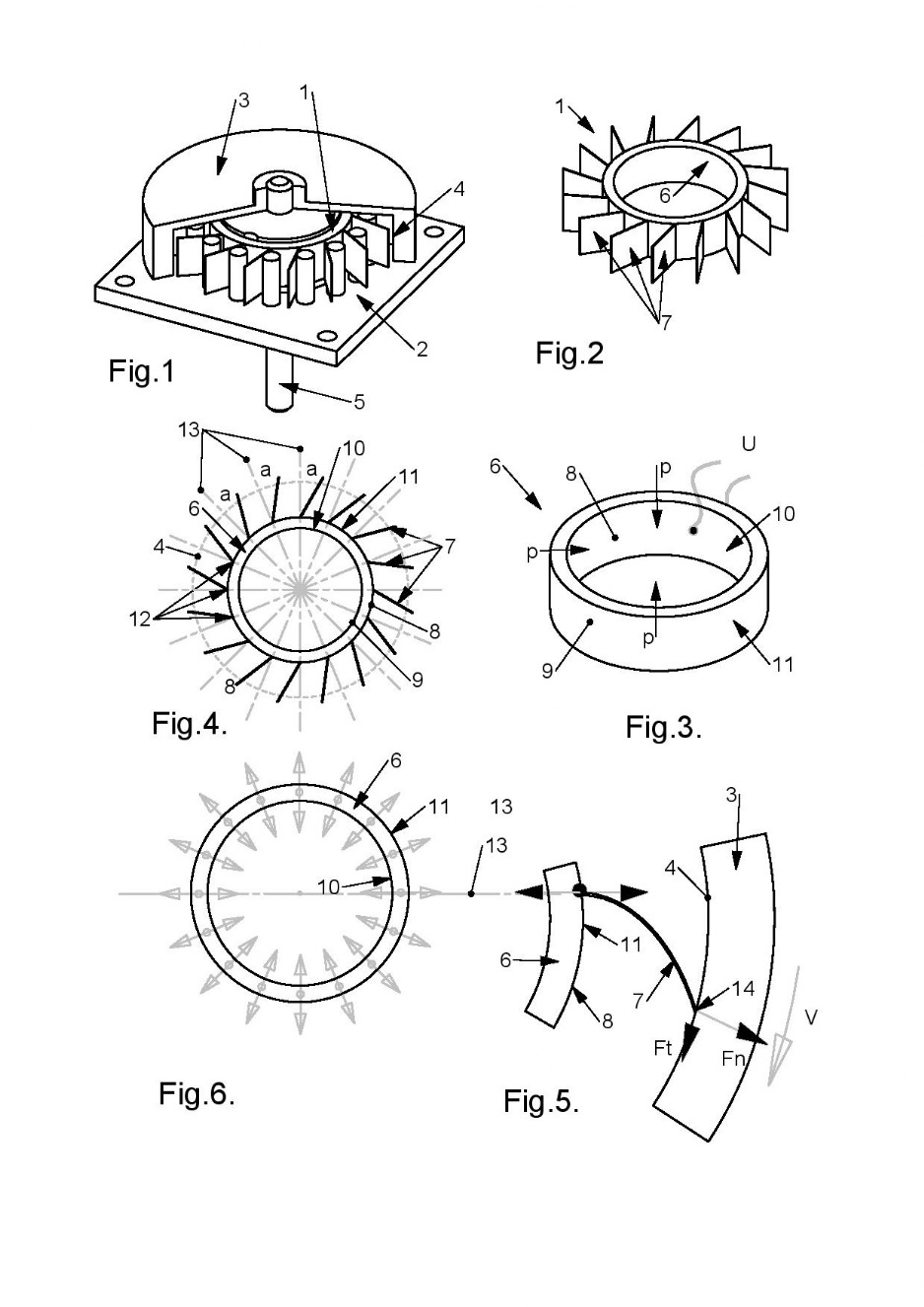
Actuator 1 (see figure 2) consists of a thin-walled piezoelectric ring 6 with attached thin elastic plate pushers 7.
The piezoelectric ring 6 (see figure 3) has metal electrodes 10 and 11 on its inner 8 and outer 9 cylindrical surfaces.
The piezoceramic of ring 6 is polarized normally to the surfaces of electrodes 10 and 11.
Electrodes 10 and 11 are equipped with terminals 12, 13 for connecting the actuator 1 to the alternating electric voltage U.
In the actuator 1, the pushers 7 (see Fig. 4) with their sides 14 are fixed on the outer cylindrical surface 9 of the piezoelectric element 6.
In the free state of the actuator 1 (see figure 4), the pushers 7 have a flat shape. The planes of the pushers 7 may coincide with the diametrical planes 15 of the ring 6, or they may be inclined to the diametrical planes 15 of the ring 6 at an angle α.
The length of the pushers 7 (see Fig. 4) is chosen a slightly larger distance between the surface 9 of the piezoelectric element 6 and the friction surface 4 of the rotor 3.
Figure 5 shows a schematic drawing of a part of a motor with one pusher 7.
When assembling the motor, the pushers 7 bend slightly, as shown in FIG. 5 as a result of which the sides 16 of the pushers 7 are elastically pressed against the friction surface 4 of the rotor 3 by the elastic force of the pushers 7.
The operation principles of the WUMoRC motors:
The operation of the motors is based on the excitation in its actuator 1 of the first mode of a longitudinal acoustic wave of deformations, propagating in a thin piezoelectric ring 6 (see figure 3) along its circumference. With such a wave, all points of the body of the ring of the piezoelectric element 6 vibrate in its diametrical planes 15 (see Fig. 6).
The first mode of a longitudinal acoustic wave of deformations is excited in the piezoelectric ring 6 when an alternating electric voltage U is applied to its electrodes 10 and 11, the frequency F of which is equal to the resonance frequency of the first mode of circular oscillations of the ring Fr1.
Frequency Fr1 can be determined by the formula Fr1 = 2N / L, where:
N- frequency constant of piezo ceramics
L is the length of the midline of the circle of the piezoelectric ring.
When the actuator 1 is excited, the side 14 of the pusher 7, fixed on the surface 9 of the ring 6, oscillates in the plane of the corresponding diametrical plane 15. The vibrations are transmitted along the curved pusher 7 to its opposite side 16. On the side 16 of the pusher 7, two alternating forces Fn and Ft arise. The force Ft presses the pusher 7 against the friction surface 4 of the rotor 3, and the force Ft rotates the rotor 3 of the motor.
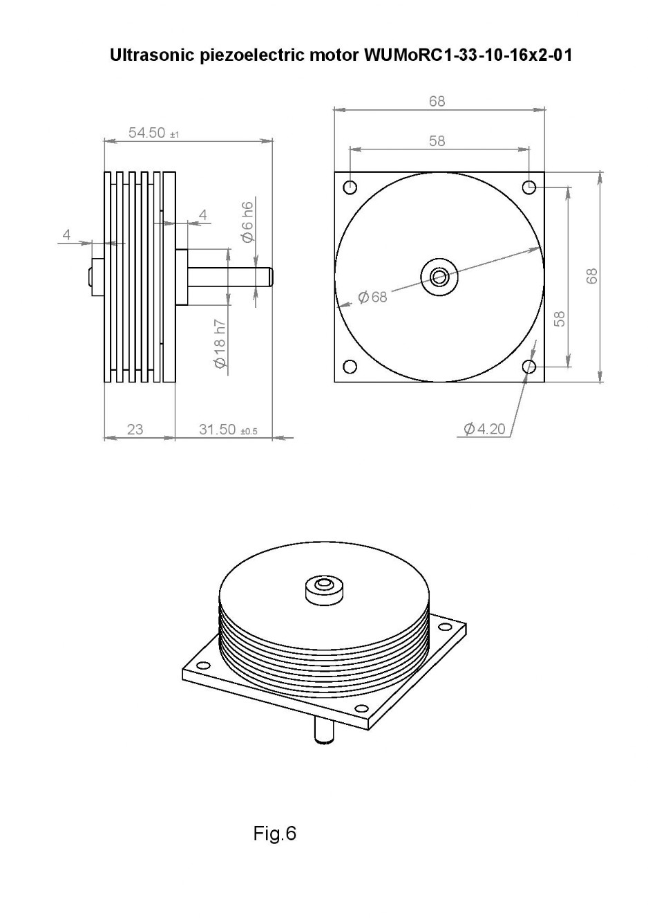
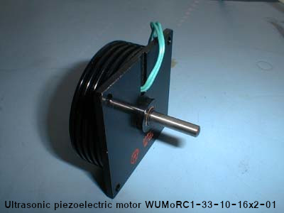
Ultrasonic piezoelectric motor WUMoRC1-33-10-16x2-01 (DPR-33N).
Parameters:
When the motor is running on a standard alternator:
When the motor is running on a standard alternator:
Excitation voltage - 60 V
With a free rotor
Exciting voltage frequency -33.6 kHz
Consumption current - 150 mA
Maximum shaft speed - 92 min-1
With the rotor stopped
Exciting voltage frequency -36.3 kHz
Consumption current - 75 mA
Maximum torque - 50 Ncm
Dimensions 68x68x24 mm
Shaft Ø6x26 mm
The external dimensions of the motor are shown in Fig. 6:
Shaft Ø6x26 mm
The external dimensions of the motor are shown in Fig. 6:
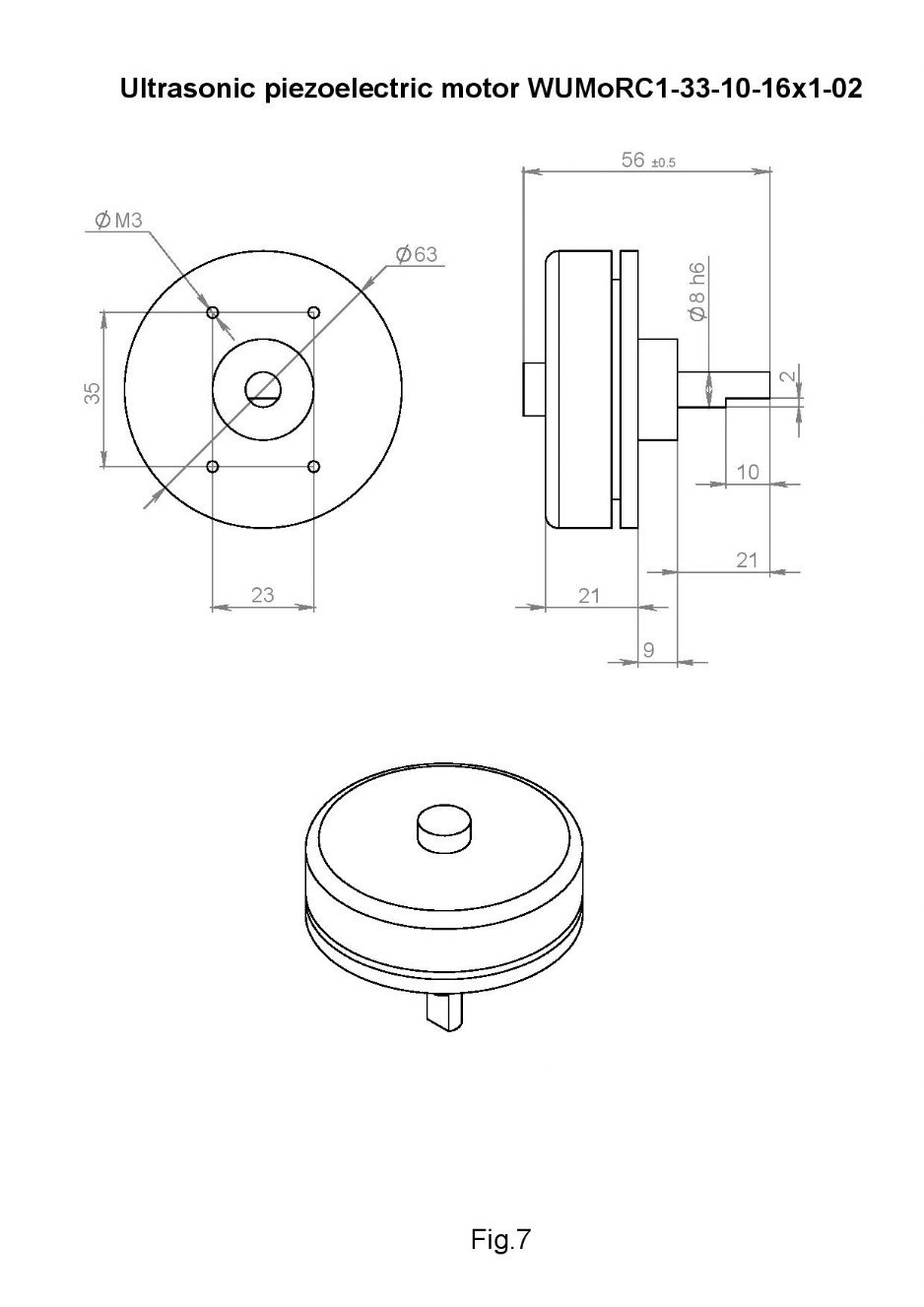
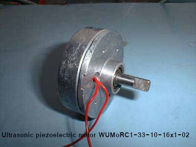
Ultrasonic piezoelectric motor WUMoRC1-33-10-16x1-02 (DPR-32N).
When the motor is running on a standard alternator:
Excitation voltage - 60 V
With a free rotor
Exciting voltage frequency -33.6 kHz
Consumption current - 150 mA
Maximum shaft speed - 92 min-1
With the rotor stopped
Exciting voltage frequency -36.3 kHz
Consumption current - 75 mA
Maximum torque - 50 Ncm.
Parameters:
When the motor is running on a standard alternator:
Excitation voltage - 60 V
With a free rotor
Exciting voltage frequency -33.6 kHz
Consumption current - 150 mA
Maximum shaft speed - 92 min-1
With the rotor stopped
Exciting voltage frequency -36.3 kHz
Consumption current - 75 mA
Maximum torque - 50 Ncm.
Dimensions 68x68x24 mm
Shaft Ø6x26 mm
The external dimensions of the motor are shown in Fig. 7: