Ultrasonic piezoelectric lock - Wischnewskyi Ultrasonic Motors


APPLICATIONS
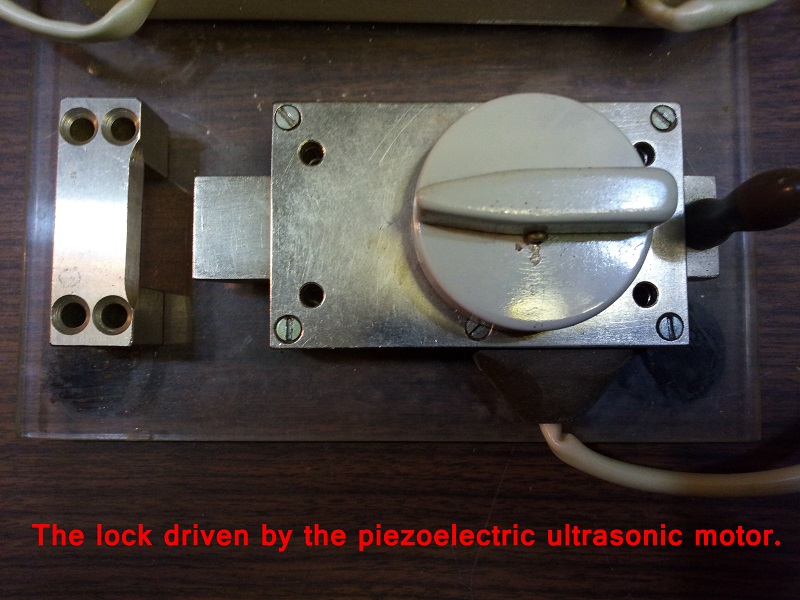
Ultrasonic piezoelectric door lock.
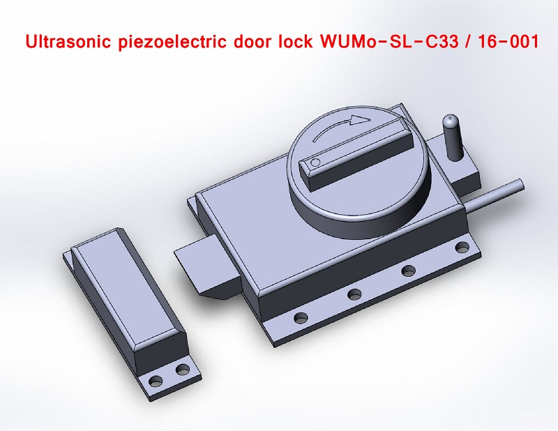
Wischnewskiy Ultrasonic Motors has developed a prototype of a door lock which is driven by the piezoelecric ultrasonic motor. The door lock is designed according to the classical scheme - it consists of a body in which the lock movable bar is driven by an ultrasonic piezoelectric motor. This novel design can be patented. We invite firms interested in further development of this project for cooperation.
Ultrasonic piezoelectric door lock WUMo-SL-C33 / 16-001.
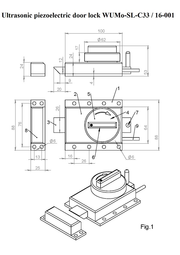
WUMo-SL-C33 / 16-001 lock is an electrically operated surface-mounted lock. The lock is driven by an ultrasonic piezoelectric motor. The lock is controlled by an electronic digital block, which can have a push-button control panel or an infrared control panel or a radio control panel, or another type of control panel. WUMo-SL-C33 / 16-001 lock is intended for installation on doors of houses, apartments, warehouses, or on doors of other premises where reliable protection against opening is required. The design of the lock WUMo-SL-C33 / 16-001 and its dimensions are shown in Fig. 1. The lock contains a mounting plate 1 on which the lock body 2 with a movable bar 3. On lock body 2 there is an ultrasonic motor 4 with a rotor 5. A rotary handle 6 is installed on rotor 5. The strike plate 3 is equipped with a movable handle 7. The lock has a locking bracket 8. The motor is connected to the control unit using cable 9.
Technical Data:
Supply voltage - 60 V
Supply voltage frequency - 33 kHz
Current consumption - 0.15 A
Closing and opening speed lock - 1 s
Maximum force, developed by a movable bar - 10 N.
The operation principle of the ultrasonic piezoelectric door lock:
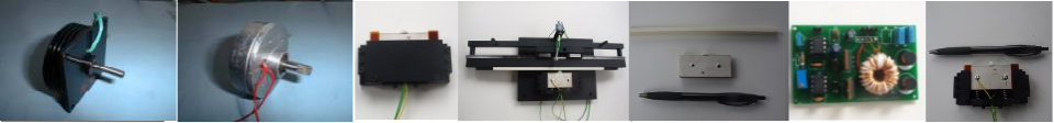
The operation of the lock is based on the use of a direct-drive ultrasonic piezoelectric motor 4. When an exciting electric voltage enters the electrodes of the piezoelectric actuator of the ultrasonic motor 4, its rotor rotates 5. The rotational movement of the rotor 5 is converted by a special mechanism located in the housing 2 into the translational movement of the strike movable bar 3. The lock has two end positions of the striker plate 3. The movable bar 3 is fully pushed into the lock body 2 - the “open” position. The movable bar 3 is fully extended from the lock body 2 - the “closed” position. Figure 1 shows the lock in the final position of the striker plate 3 "closed". If the lock is in the "open" state, then the rotation of the rotor 5 leads to the closure of the lock. If the lock is in the "closed" state, then the rotation of the rotor 5 leads to the opening of the lock. In either case, the rotary knob is positioned horizontally, with a dot at the right or with a dot at the left. In addition, the lock has two intermediate states that allow you to use the lock as a latch. In intermediate states, the rotary knob 6 is positioned vertically, with a point at the top or with a point at the bottom. Turning the movable handle 6 in the direction of the arrow allows you to manually close and open the lock from the side of the room.